In the field of Computational Fluid Dynamics (CFD), the path from a computer-aided design (CAD) model to a high-fidelity simulation result is notorious for its bottlenecks. Among these steps, volume meshing—the process of dividing a continuous physical domain into millions of discrete geometric cells—is traditionally the most labor-intensive. When dealing with complex, production-grade CAD geometries characterized by intricate features, microscopic tolerances, and dirty topological data, human intervention becomes an expensive necessity. Engineers frequently spend days cleaning surfaces, repairing gaps, and manually adjusting mesh controls. To scale simulation throughput and drive rapid design cycles, organizations must move away from manual intervention and transition toward hands-free, fully automated volume meshing pipelines.
The Bottleneck of Manual CAD Repair and Meshing
Traditional CFD workflows treat CAD preparation and volume meshing as interactive, visual tasks. An engineer imports a geometric model into a pre-processing graphical user interface, inspects it for overlapping surfaces, stitch errors, or missing faces, and manually applies patch repairs. Once the geometry is clean, the engineer manually defines mesh refinement zones around critical flow features, such as boundary layers or sharp trailing edges.
While this hands-on approach grants fine control over mesh quality, it creates an agile-killing operational bottleneck. It makes the simulation pipeline highly dependent on individual human skill and creates a severe throughput limit. In an industrial R&D environment where design variants change daily, relying on manual meshing prevents the deployment of automated parametric optimization, digital twins, or cloud-based design exploration. To break this logjam, the volume meshing process must be transformed into a programmatic execute-and-forget pipeline.
Shifting to Robust, Surface-Insensitive Meshing Algorithms
Achieving hands-free automation requires a fundamental shift in the underlying meshing algorithms. Traditional conformal surface-to-volume meshers require mathematically watertight CAD surfaces to function. If a geometric model contains a microscopic gap or a duplicate surface face, the algorithm fails, resulting in punctured meshes or unresolvable cells.
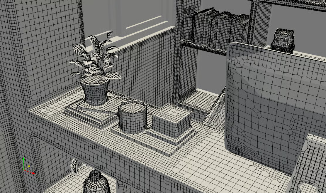
To automate the pipeline completely, organizations must leverage surface-insensitive, background-grid meshing methodologies, such as the octree-based Cartesian or hex-dominant approaches exemplified by open-source utilities like snappyHexMesh. These algorithms operate by immersing the uncleaned CAD geometry inside a predefined block of background cells. The software programmatically refines the cells intersecting the CAD surfaces, snaps the cell vertices directly onto the geometry, and discards the cells residing outside the fluid domain. Because the algorithm relies on spatial intersections rather than perfect topological connectivity, it can robustly handle imperfect, “dirty” CAD data without requiring manual surface stitching or defeaturing.
Defining Parametric Mesh Controls via Scripting
Hands-free automation is impossible if an engineer must visually click on surfaces to assign boundary layers or cell sizes. The entire meshing specification must be abstracted into text-based configuration scripts. In an automated pipeline, mesh density is controlled programmatically using geometric primitives, coordinate bounds, or descriptive naming conventions inherited directly from the CAD file.
By utilizing standardized naming strategies during the initial CAD design phase—such as labeling a specific surface as inlet_patch or turbine_blade—the automated meshing script can dynamically parse the incoming geometry. The script automatically applies predefined target cell sizes, directional aspect ratios, and viscous boundary layer insertion criteria to those specific regions. This programmatic abstraction ensures that whether the incoming CAD model is long, short, wide, or highly curved, the meshing engine applies identical, deterministic quality standards without needing a pair of human eyes to review the setup.
Algorithmic Quality Checking and Automated Smoothing
A hands-free pipeline must be intelligent enough to validate its own output. When a meshing script runs autonomously, it can occasionally produce bad cells with high non-orthogonality, excessive skewness, or negative volumes, especially near sharp concave corners. Without an automated gatekeeper, these poorly formed cells will destabilize the subsequent CFD solver, leading to simulation crashes.
To counter this, the automated pipeline must include integrated quality-checking loops. Immediately following the volume generation phase, the script executes automated analysis utilities to parse the mesh metrics against strict geometric criteria. If a cell fails to meet the required quality threshold, the pipeline automatically triggers localized topological modifications. It deploys programmatic smoothing operations, face-snapping relaxations, or cell-collapsing routines to fix the problematic regions. If the mesh cannot be repaired algorithmically, the script throws a structured error flag, preserving the integrity of the downstream solver pipeline.
Integrating the Meshing Pipeline into CI/CD and Cloud Workflows
Once the volume meshing engine is fully scripted and self-validating, it can be integrated into broader enterprise DevOps workflows. Volume meshing can be treated similarly to software compilation, triggered automatically whenever a designer pushes a new CAD iteration to a centralized Product Lifecycle Management (PLM) repository.
Using continuous integration (CI) runners, the automated meshing script can be deployed directly onto scalable cloud computing infrastructure or on-premise High-Performance Computing (HPC) clusters. The geometry is automatically pulled, meshed in parallel across dozens of CPU cores, verified for quality, and passed directly to the fluid dynamics solver without a human ever launching a GUI. This seamless integration transforms CFD from an isolated, artisanal task into an industrialized, continuous data pipeline that constantly feeds performance metrics back to the product design team.
The Technical Execution of Hands-Free Infrastructure
Building an enterprise-grade, hands-free meshing pipeline demands a unique intersection of skills, requiring a deep understanding of computational geometry, software scripting, Linux systems architecture, and fluid dynamics. Organizations often struggle to transition away from traditional commercial pre-processors because configuring open-source automated meshing tools to work flawlessly across a wide, unpredictable array of CAD inputs requires significant upfront development. The complexity of writing robust scripts that gracefully handle geometric edge cases can easily overwhelm internal engineering teams who are focused on core product development.
If your company aims to eliminate manual pre-processing bottlenecks and implement a fully automated simulation workflow, Tensor CFD can build the foundational infrastructure for you. We specialize in helping companies develop custom, in-house CFD software built upon a ruggedized OpenFOAM backbone tailored precisely to your specific industrial applications. Our team can engineer a turnkey, hands-free volume meshing pipeline that ingests raw CAD models, applies smart parametric text-based controls, algorithmically corrects cell defects, and outputs solver-ready computational grids completely autonomously. By embedding the automated robustness of OpenFOAM’s advanced meshing utilities within a tailored corporate application, Tensor CFD removes the human bottleneck from your simulation workflow—allowing your engineering team to scale design exploration endlessly, eliminate commercial software licensing constraints, and accelerate your time-to-market.